Precision and the definition of tolerance
We understand the perspectives of our customers
We supply our adaptive moulds to different industries and materials and assist our customers in optimizing their manufacturing processes. The precision of our adaptive technology is one of the benefits our customers value when choosing us as supplier.
We recognize that our tolerances are pivotal in our customers manufacturing process, as they will determine how well each manufactured panel fits in the final assembly, structurally and esthetically. We have experienced that industries have different requirements in terms of manufacturing tolerances, so it is important to consider this aspect in the process of purchasing and adaptive mould.
Our engineers are often consulted in the process where customers evaluate the different options, we offer in choice of adaptive mould specifications. We strive to assist our customers in determining the best possible specification that is fit-for-purpose, as we know this will eliminate future concerns and problems in our customers manufacturing process.
All of our adaptive moulds are delivered with certain tolerance values specified. The values can be found in the adaptive mould specification document. This document can always be requested at Adapa´s main office in Aalborg, with reference to the unique adaptive mould Adapa Id. Number.
Tolerance definition in Adapa
In the adaptive mould specification document and in our dialogue with our customers we relate to the term “Tolerance” based on a set of definitions.
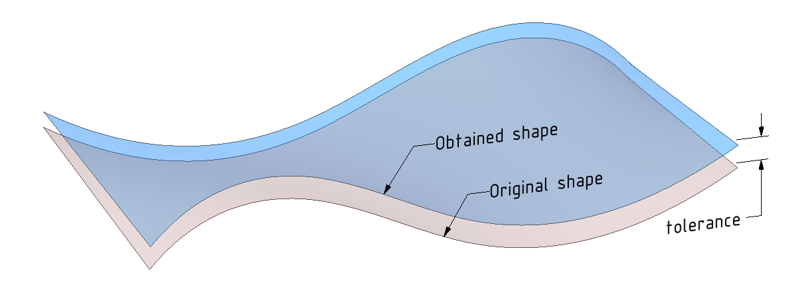
A tolerance is an acceptable amount of dimensional variation, where the obtained shape on top of the adaptive mould is still considered within the specification of the ideal dimension. It is defined by lower and upper clearance (+X/-Y).
The tolerance +X/-Y means that, any taken point on the obtained surface of the given shape may deviate +X/-Y mm in vertical direction from the ideal CAD shape.
Determination of adaptive mould tolerance
There are several steps into determining the overall tolerance that affects the final obtained shape:
Mechanical components
– each mechanical component has its own manufacturing tolerances which must not deviate more than the given engineering tolerances. The buildup of these tolerances regards to every mechanical component result in final overall tolerances that include all mechanical components and their interaction.
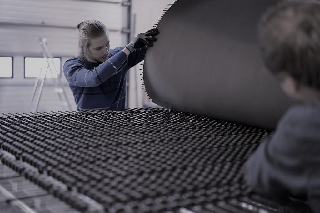
Flexible grid
– the combination of rods, joints and magnets ensures that the obtained shape is as close as possible to the ideal one given in CAD. It also supports the flexible membrane that finally gives the surface you can cast the panels on. The interaction between the components in the flexible grid have certain impact on the tolerances. It is safe to say that the more complex the shape, the lower the radius and the bigger the size, the deviations will be of course bigger.
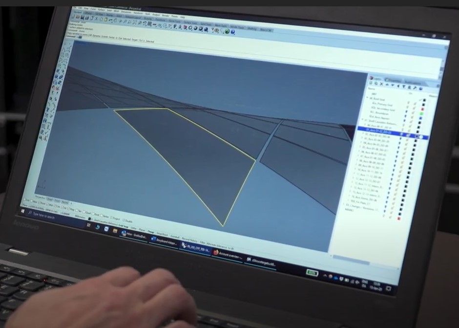
Software
– the Adapa Tools software (plug-in for Rhino 6), computes the position for each actuator so that the resulting shape on top of the membrane is as close as possible to the ideal CAD surface. This position-value is shown at the time of creating a panel in Rhino and different for each shape. This value also represents the minimum achievable tolerance.
Laser projector
– the supplied projector stems from a sub supplier, and works within the common industry tolerance of ± 0.2mm/m. The laser projector is placed above the adaptive mould at a certain height. The minimum height is determined so that it covers all the Laser Reflectors necessary for calibration, and the maximum height by the desired minimum tolerances within the projections on the adaptive mould.
Maximum tolerance and average deviation
To ensure that our adaptive moulds are within specific tolerances, Adapa has evaluated and considered every step where there could be a loss of tolerances. The specified tolerance on each adaptive mould is a maximum expected value.
This means that in most cases during normal operation, the deviation will be less that the maximum and thus the average deviation is less than the specified tolerance.
Maintaining the tolerance level
Calibration of an adaptive mould, is a procedure where the overall accuracy and precision of the mould is improved. This means that service and maintenance calibration is a prerequisite for maintaining the moulds specified tolerance.
This is the reason why it is important that an adaptive mould is calibrated upon delivery and before starting to use it. If the adaptive mould has not been proper calibrated, the specific tolerance cannot be guaranteed by Adapa.
How to measure the adaptive mould is within specified tolerance
The best way to determine if the AM is within tolerance, is by comparing the dimensions of a shape(s) representative of the mould’s capabilities with the same shape(s) reproduced on the mould.
The simplest way, but also with worst reliability, is to measure the corner to corner dimensions of the shape.
It is also possible to obtain a 3D measurement of the surface of the mould as well as the projected lines. The two most common methods are via photogrammetry or with a laser tracker. Photogrammetry allows for a closer measurement of the surface but has in general less accuracy and precision. The laser-tracker is considered the gold standard for 3D measurements; however, it is more difficult to capture the relevant dimensions.
Regardless of the method used, the measured point cloud can be aligned with the CAD model to determine if the deviations are within the specified tolerance.